How to Build a Bench Power Supply From ATX - Part I
I needed a bench power supply for testing, fixing, and building electronics and IoT projects. I could have bought one, but I had an old ATX power supply gathering dust - so I recycled it into a lab-grade bench supply with fixed voltages, USB outputs, and a variable 1.25-25V rail.
This is Part 1 of a two-part series. Part 1 covers the electronics and panel wiring. Part 2 will build the enclosure.
Safety first: An ATX power supply contains large electrolytic capacitors that can hold a dangerous charge even after the unit is unplugged. The standby 5VSB rail is always live when the supply is connected to mains. If you are not comfortable working with mains-powered equipment, buy a bench supply instead. Discharge all capacitors before handling the open PSU.
Requirements
I defined these outputs based on the projects I typically build:
- One 3.3V output
- Two +5V outputs
- One +12V output
- One -12V output
- Two USB outputs (5V, for powering microcontroller boards)
- One variable output: 1.25-25V, 0-2A (using a Boost Buck converter)
- Power switch (mains on/off)
- Power-on LED (red)
- Standby LED (green)
- Independent switch for the variable output
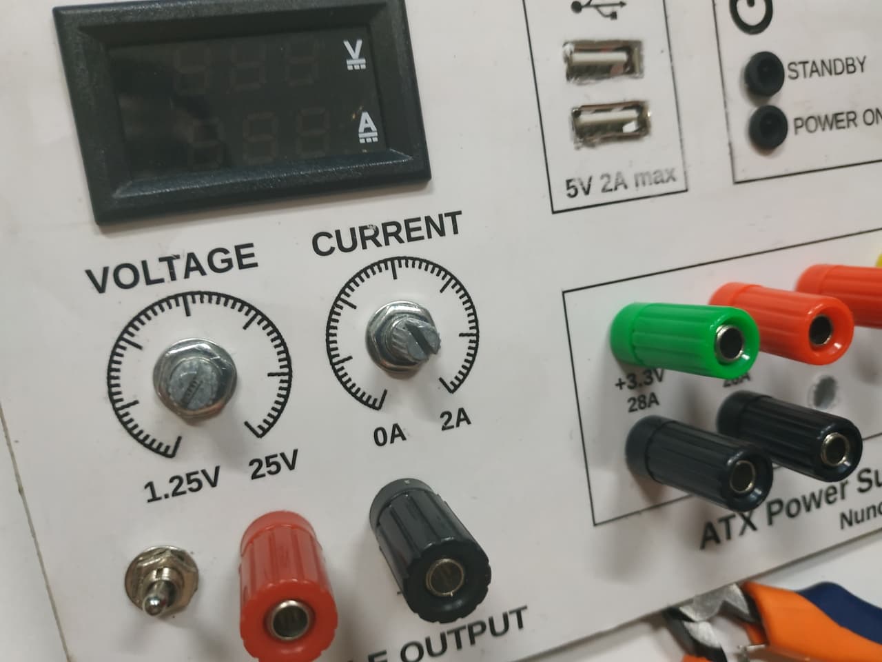
- Embedded digital multimeter for the variable rail
Components Used
| Part | Spec / Model | Notes |
|---|---|---|
| ATX power supply | Generic 500W unit (check your label for rail ratings) | Any standard ATX will work; match your current needs to the rail ratings |
| Boost Buck converter | LM2596-based module (constant voltage/current) | Widely available; solder terminals directly for reliability |
| Digital panel meter | 0-30V / 0-10A LED display (two-wire or three-wire) | Calibrate with a multimeter before mounting |
| Binding posts | 5 pairs (red/black, panel-mount, 20A rated) | One pair per fixed output + one for variable |
| USB jacks | 2x female USB-A (panel-mount) | Connect to 5VSB for always-on or +5V for switched |
| Toggle switches | SPST, panel-mount, 3A rated | One for mains, one for variable output |
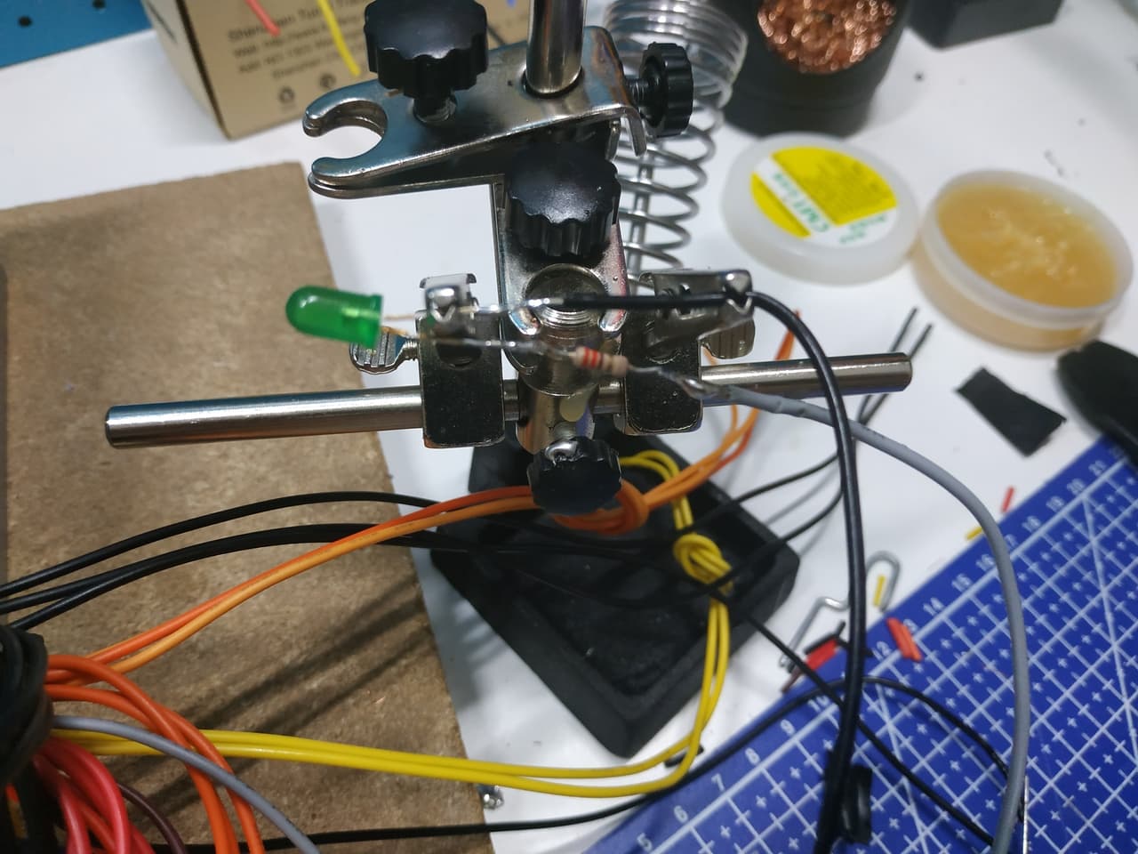
| LEDs | 5mm red + green, with 220 ohm current-limiting resistors | Red = power on, green = standby |
| Acrylic sheet | 3mm, laser-cut or hand-drilled | For the front panel |
Substitutions: The LM2596 can be replaced with any CC/CV buck converter module. The panel meter can be any 0-30V LED display - just verify the power input matches your supply rail (some need isolated power).
Circuit Overview
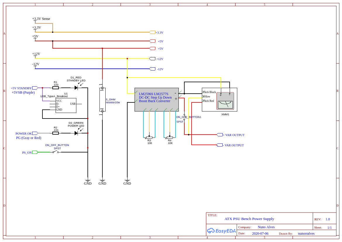
The schematic shows the full wiring. Here is how it breaks down:
- Fixed outputs: Each ATX voltage rail (3.3V, +5V, +12V, -12V) is wired directly to a pair of binding posts on the front panel. The ATX ground (black wires) is common across all outputs.
- USB outputs: +5V and ground from the ATX are wired to USB-A jacks. These provide 5V for microcontroller boards and small projects.
- Variable output: The +12V rail feeds the Boost Buck converter's input. The converter's output goes to its own pair of binding posts through a toggle switch, so the variable rail can be turned off independently.
- Digital panel meter: Wired across the variable output terminals to display voltage (and current, depending on the meter model).
- LEDs: Power-on LED (red) is wired to the switched +5V rail. Standby LED (green) is wired to 5VSB (the always-on standby rail), so it lights whenever the ATX is connected to mains.
Critical wiring note: The ATX power supply will not start unless you short the PS-ON wire (usually green) to ground. This is typically done with a toggle switch - closed = PSU on, open = PSU off. Double-check your ATX pinout before wiring: the green PS-ON and grey Power-Good wires are easy to confuse.
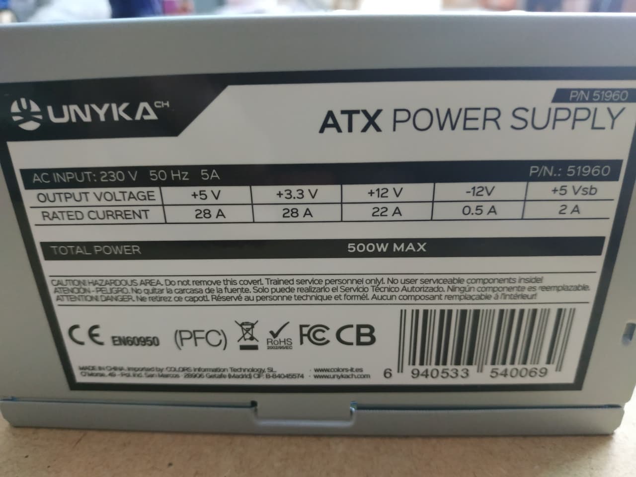
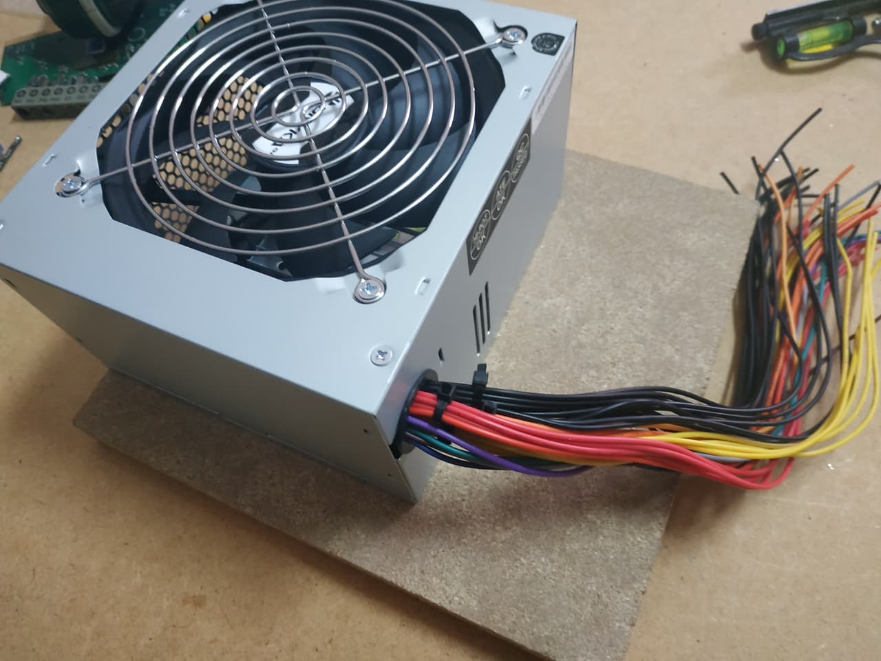
I used this ATX, with output voltages and currents identified on it
Front Panel
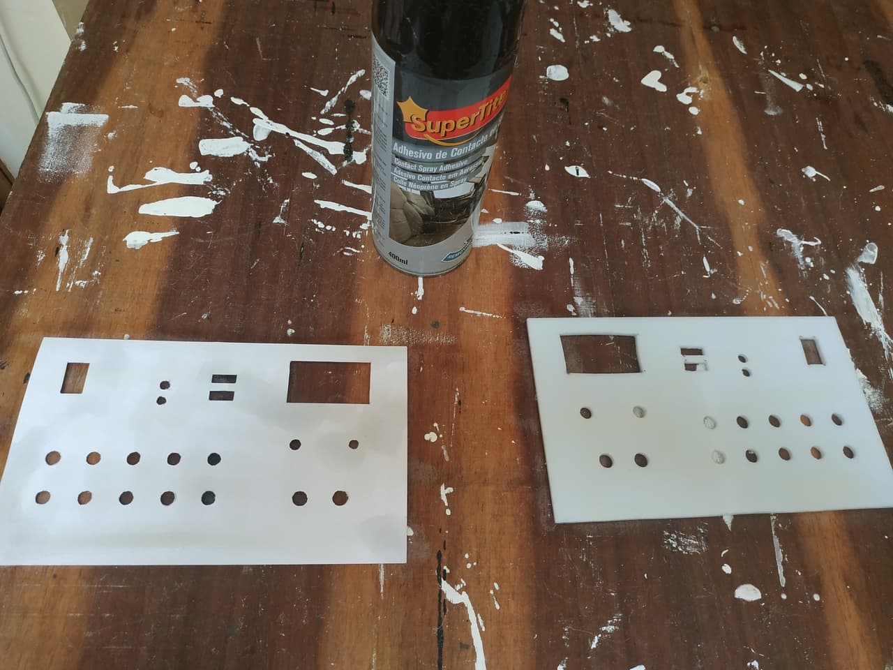
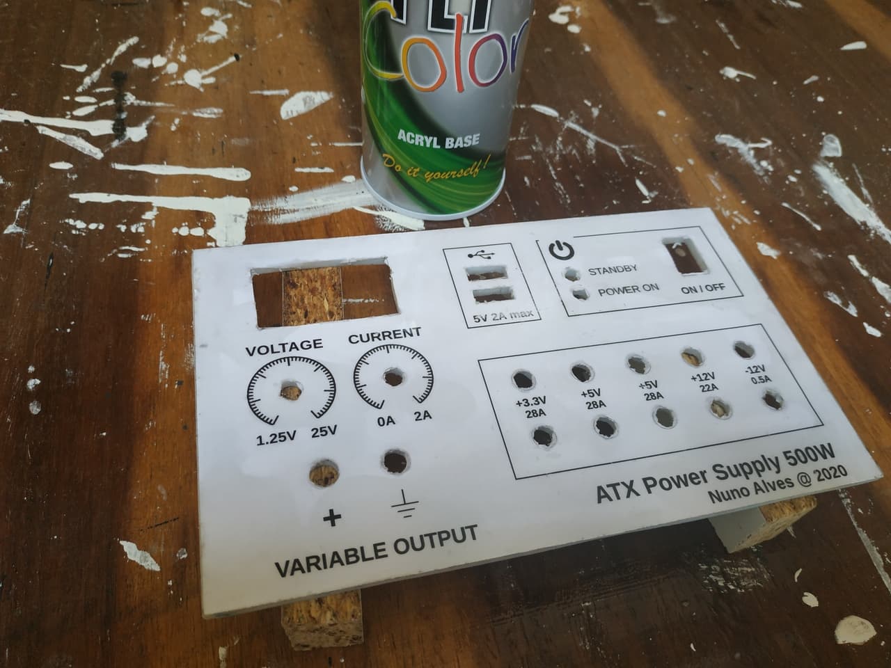
I designed the front panel layout, printed it, and transferred the design to an acrylic board.
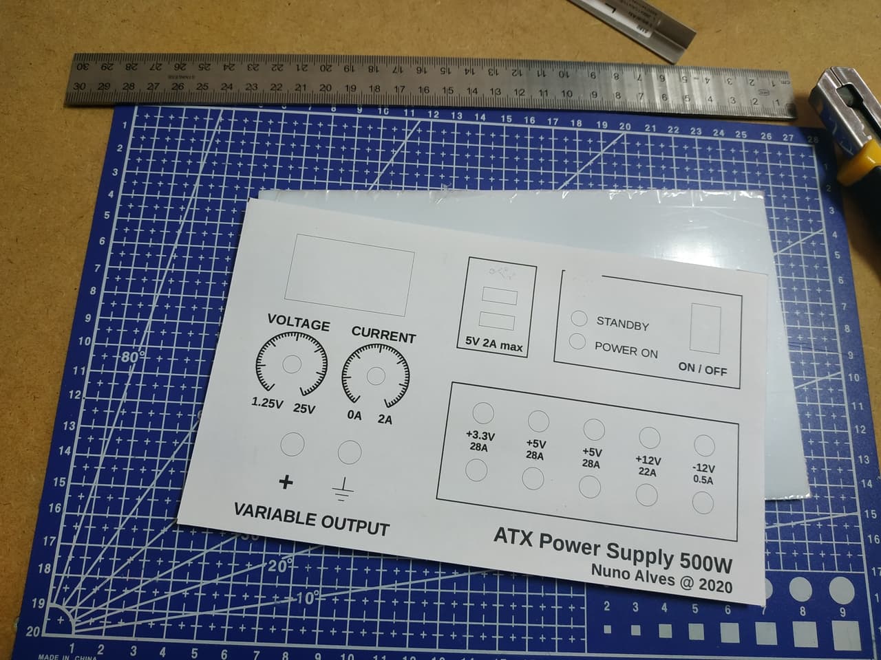
Then I drilled it according to the design and glued a new printout. After that, I've applied an acryl base to it
Wiring
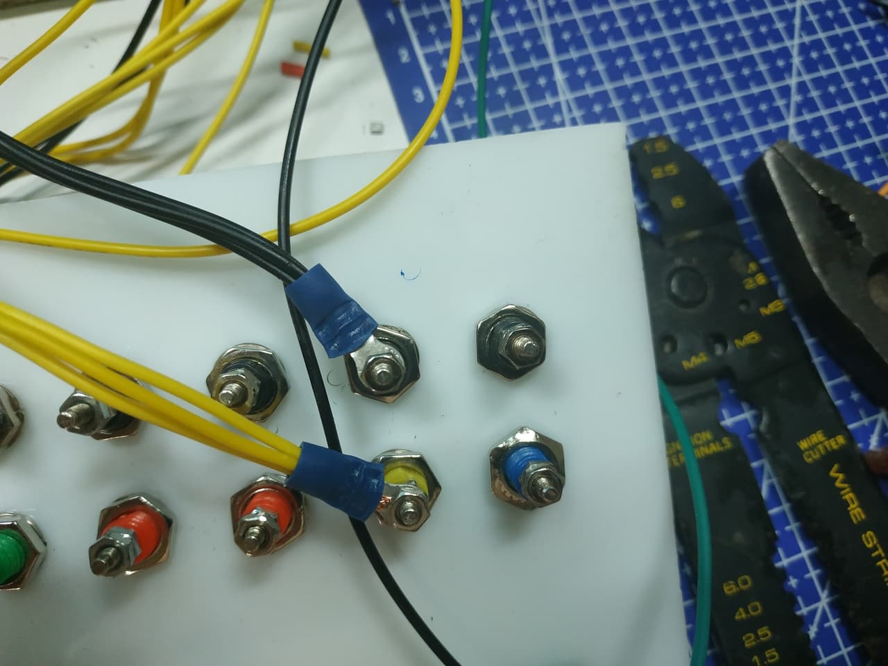
Start by cutting the ATX connector block off and separating wires by voltage (ATX uses standard colour coding: yellow = +12V, red = +5V, orange = +3.3V, blue = -12V, black = GND, green = PS-ON, grey = Power-Good, purple = 5VSB). Group wires by voltage - I bundled 3 wires per rail to handle the rated amperage without single-wire overload.
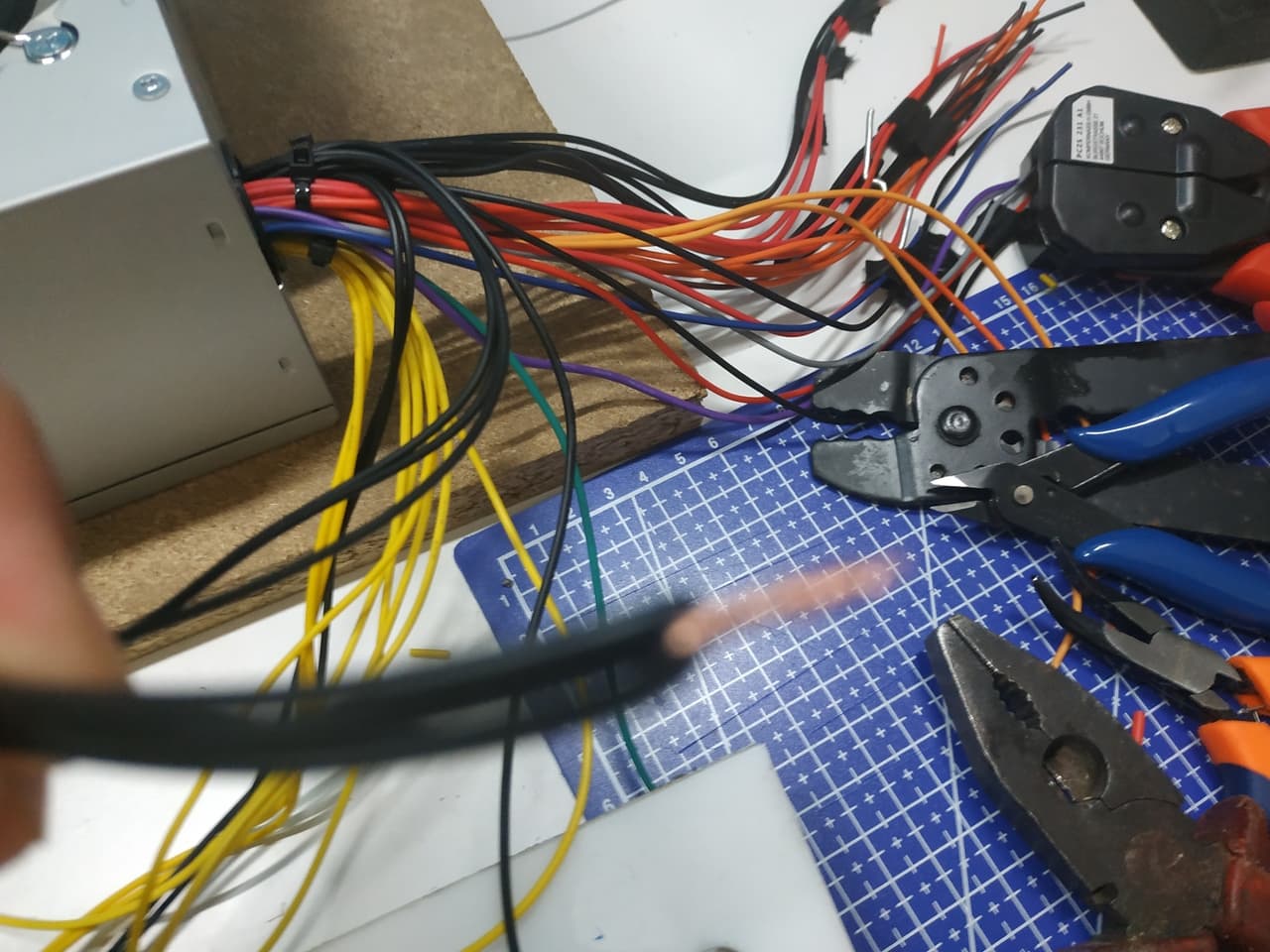
Gotcha: ATX wires are thin (18-20 AWG) but multiple wires in parallel share the current. Three parallel wires per rail is safe for the typical ATX rating. Do not rely on a single wire for high-current loads.
Variable Output Wiring
For the variable section, I unsoldered the Boost Buck converter's trim potentiometers and replaced them with panel-mount potentiometers on long wires, so the controls sit on the front panel. I also soldered the +12V input from the ATX and the digital panel meter connections directly to the converter board - no sockets, to avoid intermittent contact.
Power Outputs, USB, and LEDs
Wire the binding posts to their respective ATX rails. Wire the USB jacks to +5V and GND. Wire the power-on LED (red) through a 220 ohm resistor to the switched +5V rail, and the standby LED (green) through a 220 ohm resistor to the 5VSB rail.
Gotcha: The standby LED (green) will always be on when the ATX is plugged into mains, even when the main power switch is off. This is intentional - it confirms the ATX has mains power. If it is off, check your mains connection before troubleshooting anything else.
Final Result
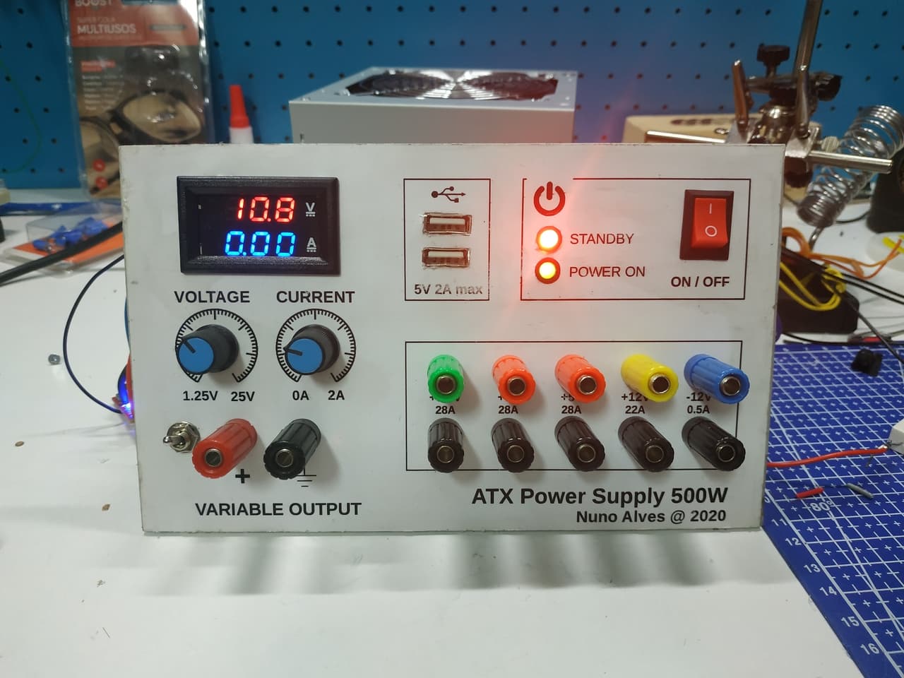
The panel is fully wired, tested, and working. Every fixed output delivers within ATX spec, the variable output adjusts smoothly from 1.25V to 25V, and the panel meter reads accurately.
Honest Take
A few things I would do differently next time:
- Panel-mount the Boost Buck converter directly rather than using extended potentiometer wires. The wires introduce noise on the voltage adjustment and the potentiometer mounting is less sturdy than I would like.
- Label the back of the panel with wire colours and rail assignments before assembling. Once everything is wired, tracing a loose connection means disassembling the whole bundle.
- Test the variable output under load before final assembly. The LM2596-based modules are rated for 2A but some cheap variants struggle above 1.5A without active cooling.
- Add a fuse on the variable output. The ATX has over-current protection on its rails, but the Boost Buck module does not - a dead short on the variable output could damage the module before the ATX protection kicks in.
The build works well for everyday bench use. If I were doing it again, I would consider a dedicated bench supply kit for the variable section and use the ATX only for the fixed rails - the Boost Buck converter adds complexity that a proper bench supply module would avoid.
What is Next
Part 2 will cover building a suitable enclosure for the panel - measurements, material choices, ventilation, and mounting.